Choosing a 12V Motor With Gear starts with the real load, not the largest torque figure on a product page. Will the motor lift a small hatch, turn a wheel, or move a mechanism against friction? Each task needs a different balance of speed, torque, current, and size. Small details matter. A gearmotor that turns freely on a workbench may stall when a wheel meets carpet or a linkage reaches its end stop.
The U.S. Department of Energy’s 2014 report, Improving Motor and Drive System Performance, notes that motor-driven systems account for roughly 68% of electricity use in U.S. manufacturing. That broad figure does not describe small 12-volt gearmotors, but it highlights why matching a motor to its load matters. For selection, compare rated voltage, no-load speed, rated torque, stall current, gearbox ratio, and duty cycle. Check the driver and power supply against startup and stall current, too; a supply rated only for normal running may cut out under load. One thing is easy to overlook: the load rarely behaves exactly like a bench test. Leave practical margin, confirm the manufacturer’s data sheet, and test the assembly in its actual operating position. A tidy calculation helps, but it cannot reveal every jam, vibration, or alignment issue.
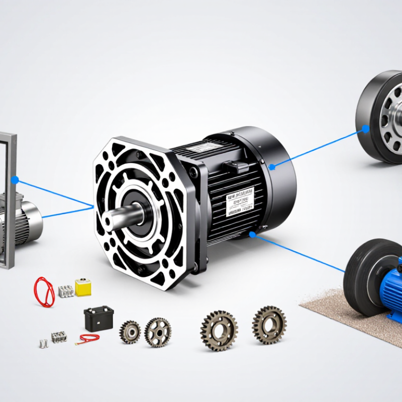
A 12V geared motor should match the motion your mechanism needs, not just fit its space. Define the output speed, travel distance, direction changes, and start-up frequency. A small wheel moving a light panel needs different torque from a motor lifting a loaded arm. Estimate the load at the gearbox shaft, including friction and acceleration. Then check that the motor’s rated output speed and torque suit the real task. Stall torque is not a safe continuous operating target.
Duty cycle matters just as much. A motor that runs for ten seconds and rests for a minute may handle a different load than one running continuously. Repeated starts, tight enclosures, and warm surroundings can increase heat. Check the motor’s rated duty and operating temperature, and leave a margin rather than sizing right to the limit. Small details matter. I have seen a mechanism work on a bench, then slow down once its wiring and full load were added. That estimate deserved another test.
Tips: Record the load, target speed, run time, and rest time before comparing motors. Test with the actual supply voltage and mounted gearbox. Measure twice. If the unit becomes hot or motion slows, reassess the load and duty cycle. Don’t assume a gearbox will hold a load safely when power is off.
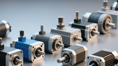
Choose a 12V geared motor by working backward from the load, not by voltage alone. Estimate the required output speed, then calculate the torque needed at the shaft. For a wheel, torque depends on tractive force and wheel radius; friction and startup loads add more. Leave a practical margin, but avoid excessive oversizing, which can waste battery power and create heat.
A 30:1 gearbox reduces motor speed to about one-thirtieth while multiplying torque by up to 30 before losses. Real output torque is lower. Check the datasheet’s continuous torque, not just stall torque. Stall torque is a brief limit, not a safe operating point. A motor under heavy load at low speed can draw high current and overheat. Test current during startup and under the heaviest expected load.
Efficiency matters. The U.S. Department of Energy’s 2014 motor-systems assessment estimated that motor-driven systems used about 69% of U.S. manufacturing electricity. That figure does not describe small 12V gearmotors specifically, but it highlights the cost of poor matching at scale. Compare gearbox efficiency, duty cycle, and available current together. I would test the complete mechanism, too. Friction estimates are often optimistic; a bench test may reveal that a seemingly suitable ratio stalls on carpet or during a cold start.
Choose the gearbox type to match the load, mounting space, and duty cycle—not just the advertised torque. Spur gearboxes suit straightforward, cost-conscious designs with parallel shafts. Planetary gearboxes fit compact assemblies needing higher torque density. Worm gearboxes provide right-angle output and large reductions, but can generate more heat and lose more power. Measure the load first. A gearbox’s real performance depends on its design and operating conditions.
Set the reduction ratio by dividing motor speed by the required output speed. For example, a 3,000 rpm motor turning a 150 rpm shaft needs a 20:1 ratio. Theoretical output torque rises with the ratio, but gearbox losses reduce the result. Check rated torque, startup load, backlash, and allowable input speed; also confirm the 12V motor can supply the required current. Small details matter. The U.S. Department of Energy’s Improving Motor and Drive System Performance report estimates motor-driven systems use 54% of U.S. manufacturing electricity, while a European Commission motor-systems study places their share near 70% of EU industrial electricity. These figures use different boundaries, but both show why efficiency deserves attention. A high ratio can look ideal on paper. Not always. Check temperature and current under the actual load before settling on it.
Estimated gearbox output speed at different reduction ratios, assuming a motor input speed of 3,000 rpm.
How to use this chart: Output speed is estimated by dividing motor speed by the reduction ratio; for example, 3,000 rpm ÷ 20 = 150 rpm. A higher reduction ratio generally lowers output speed and increases available torque, subject to gearbox efficiency and load. Spur gearboxes are often a straightforward, economical choice; planetary gearboxes offer compact designs with high torque capacity; worm gearboxes can provide large reductions and right-angle output, often with lower efficiency. Check the motor’s loaded speed, required torque, duty cycle, and gearbox ratings before selecting a configuration.
A 12V geared motor should match the electrical supply and the job it must perform. Check its rated voltage, no-load current, and current under load. The power supply must handle startup current, which can briefly rise well above the running figure. A motor that repeatedly stalls may overheat or damage its driver. Leave a sensible current margin, and confirm the specified duty cycle. Continuous operation and short bursts are not interchangeable.
Mechanical ratings matter just as much. Compare gearbox output speed and torque with the load, not only the motor’s advertised maximum torque. Check shaft size, mounting pattern, and allowable radial or axial loads. A small wheel pulling a cart on carpet needs different torque from one turning freely on a bench. It is easy to focus on torque and overlook speed; that trade-off deserves a second look. Measure twice.
Tips: Check the datasheet at the voltage you will actually use. Test the motor with the real load, and monitor its temperature after several minutes. Also review the operating temperature range and enclosure rating. Dust, splashes, and poor ventilation can shorten service life. An IP rating helps, but it does not answer every installation question. When details are missing, ask the supplier rather than guessing.
How to Choose a 12V Motor With Gear? Confirm Fit, Control, and Safe Operating Conditions
A 12 V geared motor must fit the mechanism and its workload, not just the available power supply. Measure the mounting face, shaft diameter, and usable length; even a few millimeters can prevent a clean installation. Then match output speed and torque to the load, including startup resistance. A conveyor that starts under load needs more starting torque than one that runs freely. The U.S. Department of Energy’s 2014 Improving Motor and Drive System Performance sourcebook reports that motor systems use about 68% of the electricity consumed by U.S. manufacturing. That broad figure highlights why efficient sizing matters, though it does not specify a suitable motor for your application.
Tips: Check the motor’s rated voltage, gearbox ratio, duty cycle, and stall current against your controller and power supply. Leave room for airflow. Test with the real load, not only on a workbench.
During testing, monitor case temperature, noise, and current draw over a full operating cycle. Confirm that the gearbox can handle occasional load peaks, and avoid running the motor continuously at stall. Keep wiring secure and protect moving shafts from accidental contact. If the motor gets unexpectedly hot, stop and reassess the load or duty cycle; a rating label alone cannot reveal every installation problem.
| Selection Check | What to Confirm | How to Evaluate It | Practical Guidance |
|---|---|---|---|
| Supply voltage | The motor’s rated voltage and the voltage available at its terminals under load. | Check the motor data sheet and measure the supply during operation. Include voltage drop in cables, connectors, and switches. | A “12 V” system should not be assumed to deliver exactly 12 V in every condition. Keep the motor within its manufacturer-specified voltage range. |
| Required output speed | Gearbox output speed at the expected load, not just the no-load speed. | For a simple estimate, output speed ≈ motor speed ÷ gear ratio. For example, 3,000 rpm ÷ 30:1 ≈ 100 rpm before load effects. | Actual speed changes with load, supply voltage, motor characteristics, and gearbox losses. Verify the loaded operating point in the specifications or by testing. |
| Required output torque | Torque needed to start, move, or hold the mechanism during its intended operation. | Estimate the load torque at the gearbox shaft, including friction, acceleration, and any changing load. Check both continuous and peak torque ratings. | Do not use stall torque as a continuous operating rating. It is a short-duration condition and can cause high current and rapid heating. |
| Gear ratio and efficiency | Whether the reduction ratio provides a useful balance of speed and torque. | Approximate output torque as motor torque × gear ratio × gearbox efficiency. For example, 0.02 N·m × 30 × 0.70 ≈ 0.42 N·m. | The example is illustrative only. Use the selected gearbox’s published efficiency and rated torque; efficiency varies with design, ratio, speed, and load. |
| Starting and peak load | Whether the motor can start the mechanism and handle brief load increases. | Compare the required starting and peak torque with the manufacturer’s permitted intermittent ratings. Consider the load’s inertia and any binding or impacts. | Allow an appropriate design margin for uncertainty, but do not exceed the motor or gearbox’s specified limits. A motor that repeatedly stalls is not properly sized. |
| Current and driver capacity | Normal running current, startup current, and stall current, plus the controller’s ratings. | Check all current figures in the motor data sheet. Confirm that the power supply, wiring, connectors, fuse, and motor driver can handle the expected load and transients. | Startup or stall current can be much higher than running current. Provide suitable current protection and do not select a driver using only the no-load current. |
| Duty cycle and temperature | How long and how often the motor runs, and whether it has time to cool. | Match the application to the stated continuous or intermittent duty rating. Monitor motor and gearbox temperature during a representative test cycle. | Enclosures, high ambient temperature, frequent starts, and heavy loads can reduce heat dissipation. Stay within the manufacturer’s temperature limits. |
| Mechanical fit | Gearbox dimensions, mounting pattern, shaft diameter and length, and permitted radial or axial shaft loads. | Compare the dimension drawing with the assembly. Check coupling alignment, shaft engagement, fastener clearance, and the load applied to the output shaft. | Do not use the gearbox output shaft to support loads beyond its rating. Use separate bearings or supports where the design requires them. |
| Control and direction | Whether the application needs on/off control, speed adjustment, direction reversal, or position feedback. | Choose a compatible controller. Reversing a brushed DC motor’s polarity reverses its direction; speed control commonly uses a suitable PWM motor driver. | Confirm the controller’s voltage and current ratings. Add appropriate braking, limit switches, or feedback if the mechanism needs controlled stopping or positioning. |
| Environment and protection | Exposure to dust, moisture, vibration, chemicals, and ambient temperature extremes. | Compare the installation conditions with the motor and gearbox protection ratings and material limits. | Do not assume a motor is sealed or suitable for outdoor use unless its specifications explicitly state so. Protect wiring and connectors as part of the installation. |
| Back-driving and holding | Whether the load can turn the gearbox when power is off, and whether it must remain in position. | Check the gearbox design and the manufacturer’s back-drive information under the actual load conditions. | A gearbox should not be treated as a safety brake unless it is specifically rated for holding. Use a suitable brake or mechanical restraint when required. |
| Final verification | Operation at the actual voltage, load, mounting orientation, and duty cycle. | Test startup, steady running, stopping, direction changes, and the most demanding expected load. Record current, speed, and temperature. | Stop testing if the motor repeatedly stalls, exceeds specified limits, or shows abnormal heating, noise, vibration, or gearbox wear. |
Note: The numerical examples are calculations for illustration, not specifications for a particular motor. Use the selected motor and gearbox manufacturer’s data for final sizing and safety checks.