Leave Your Message
Choosing the right drive system can shape an industrial plant’s productivity, safety, and operating costs. An Electromagnetic Motor offers controlled motion through electromagnetic force, making it valuable for pumps, conveyors, compressors, fans, and automated production lines. Its response can be adjusted with modern motor drives, allowing operators to match speed and torque with changing workloads. This can reduce unnecessary energy use during lighter production periods.
Performance depends on real conditions. Dust, heat, moisture, vibration, and frequent starts can affect motor life. A properly selected Electromagnetic Motor should match the machine’s load profile, duty cycle, voltage, enclosure rating, and cooling requirements. Field experience shows that installation quality matters as much as the motor itself. Misalignment, loose connections, or poor ventilation may create noise, excess heat, and early failures.
Maintenance teams also benefit from predictable inspection routines. They can monitor temperature, vibration, insulation condition, and bearing performance before a small issue becomes expensive downtime. Still, this technology is not a universal answer. Some applications require specialized motors, hydraulic systems, or other drive solutions. Selection should follow measured operating data, manufacturer guidance, and applicable safety requirements.
There is room for error.
A careful evaluation remains essential. Engineers should compare purchase price, energy consumption, control needs, maintenance access, and expected service life. When these factors are reviewed honestly, an Electromagnetic Motor can provide dependable industrial performance without relying on exaggerated promises.
Why Choose an Electromagnetic Motor for Industrial Use?
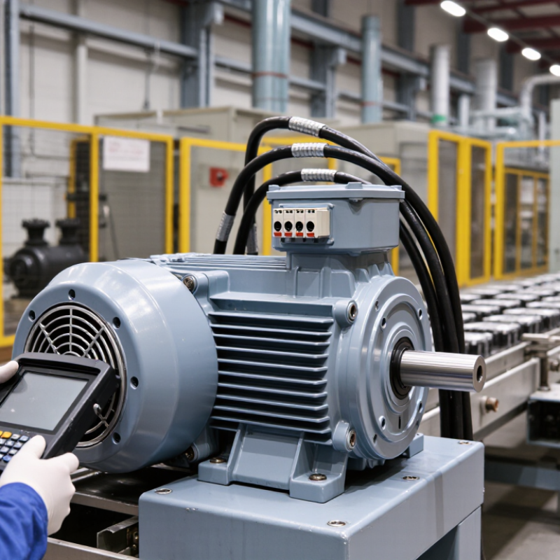
An electromagnetic motor converts electrical energy into mechanical rotation through field interaction. Current flows through windings and creates a magnetic field. That field interacts with another magnetic field, producing torque on the shaft. More current can increase torque, but only within the motor’s thermal and electrical limits. Excess current raises winding temperature and may shorten insulation life. Torque also changes with speed, load, and control settings. These relationships matter when selecting a motor for conveyors, pumps, compressors, or machine tools.
In practical commissioning, engineers should compare rated torque with the machine’s starting demand. A clamp meter, thermal sensor, and vibration check can reveal problems early. I have seen motors pass a no-load test but struggle when a conveyor is fully loaded. That result is easy to overlook. A simple calculation can mislead if friction or sudden load changes are ignored. Electromagnetic motors remain attractive because their torque response can be controlled precisely. Their performance still depends on correct sizing, ventilation, wiring, and maintenance.
Tips: Measure current during startup and normal operation. Check temperature near the windings after sustained loading. Keep a record of torque, speed, and vibration readings. Do not assume a larger motor always saves energy. Sometimes it operates inefficiently under light loads. Recheck the selection when production conditions change.
| Technical Dimension | Fundamental Relationship or Data | Typical Industrial Interpretation | Why It Matters |
|---|---|---|---|
| Electromagnetic torque | T = kT × I for a motor operating within its rated magnetic region | Torque generally increases with current until magnetic saturation, thermal limits, or controller limits are reached. | Provides predictable starting and load-handling capability for conveyors, pumps, compressors, and machine tools. |
| Torque and mechanical power | P = T × ω Power in watts = torque in newton-metres × angular speed in radians per second |
At a constant power level, available torque decreases as rotational speed increases. | Helps engineers match motor output to speed, shaft load, gearbox ratio, and production requirements. |
| Current and copper heating | PCu = I²R | A 10% increase in winding current can produce approximately 21% more resistive copper loss if resistance remains constant. | Current control is essential for efficiency, insulation life, cooling design, and overload protection. |
| Magnetic field interaction | A current-carrying conductor in a magnetic field experiences force: F = B × I × L when the conductor is perpendicular to the field. | Stronger magnetic flux density, greater conductor length, or higher current increases electromagnetic force. | This interaction is the physical basis of motor rotation and continuous torque production. |
| Synchronous speed | ns = 120f / p ns in rpm, frequency f in hertz, pole count p |
At 50 Hz: 2-pole = 3,000 rpm, 4-pole = 1,500 rpm, and 6-pole = 1,000 rpm. | Supports correct motor selection for required speed and reduces the need for unnecessary mechanical speed conversion. |
| Induction-motor slip | s = (ns − n) / ns | The rotor runs slightly below synchronous speed so that relative motion can induce rotor current and torque. | Slip is necessary for torque generation but changes with load and affects speed regulation. |
| Starting torque | Starting torque is the torque available at zero shaft speed; its value depends on motor design, voltage, current, and control method. | High-inertia or high-friction loads require sufficient starting torque and controlled acceleration. | Reduces stalled starts, mechanical shock, voltage disturbance, and production interruptions. |
| Efficiency | η = Mechanical output power / Electrical input power × 100% | Efficiency varies with motor size, load, speed, voltage, frequency, temperature, and operating point. | Higher efficiency lowers operating energy use and reduces heat that must be removed from the motor enclosure. |
| Speed control | For variable-frequency operation, motor speed is primarily adjusted by changing supply frequency while maintaining suitable voltage-to-frequency control. | A drive can provide acceleration, deceleration, speed regulation, and current limiting. | Improves process control and can reduce throttling or mechanical losses in variable-load systems. |
| Thermal operating limit | Motor temperature is affected by current, ambient temperature, cooling method, enclosure, duty cycle, and installation conditions. | Continuous operation near or above rated load requires appropriate ventilation, cooling, and overload protection. | Protects winding insulation, bearings, lubricants, and overall service life. |
| Industrial suitability | Electromagnetic motors convert electrical energy into controlled rotary or linear mechanical motion without combustion at the point of use. | They are available for fixed-speed, variable-speed, reversing, positioning, and regenerative applications. | Offers clean operation, precise controllability, repeatable torque, and compatibility with automated industrial systems. |
Note: Actual torque, current, efficiency, temperature rise, and speed depend on the motor design, rated voltage and frequency, load profile, control system, and installation conditions.