Leave Your Message

What Is a Brushless DC Motor and How Does It Work?

A Brushless Direct Current Motor converts electrical energy into controlled rotary motion without mechanical brushes. Instead, electronic switches energize stationary windings around a permanent-magnet rotor. Position sensors, or sensorless software, coordinate this switching. The rotor follows a rotating magnetic field. Quietly, precisely, and with fewer wearing parts.

The International Energy Agency reports that electric motor systems consume roughly half of global electricity. This makes motor efficiency an industrial priority, not merely a design preference. The U.S. Department of Energy also identifies motor-driven equipment as a major opportunity for energy savings in factories and commercial facilities. These figures explain the technology’s rapid use in drones, electric vehicles, pumps, medical equipment, and automated production lines.

Dr. R. Krishnan, a widely cited motor-drive researcher, describes the principle clearly: “The brushless DC motor is a permanent-magnet motor whose commutation is performed electronically.” That sentence captures the central difference from brushed motors. It also reveals a practical limitation: the motor needs a controller, careful timing, and suitable thermal management. High speed does not guarantee high efficiency. Poor tuning can create vibration, audible switching noise, or unwanted heat.

This article examines what a Brushless Direct Current Motor is and how it works. You will see the roles of the stator, rotor, Hall sensors, inverter, and back electromotive force. Real performance depends on the entire system. That point is easy to overlook. Industry reports provide broad trends, but installation conditions, load patterns, and control quality decide the final result.
What Is a Brushless DC Motor and How Does It Work?

Definition and Core Features of a Brushless DC Motor

A brushless DC motor is an electronically commutated motor without mechanical brushes or a commutator. Its rotor usually carries permanent magnets, while copper windings sit on the stationary stator. An inverter switches current through these windings in sequence. This changing magnetic field pulls the rotor around, creating continuous torque.

Its core features are clear: lower brush wear, high speed capability, compact construction, and precise electronic control. Position feedback may come from Hall sensors, encoders, or sensorless estimation from back electromotive force. The controller must match current timing with rotor position. A small timing error can produce vibration, heat, or weak starting torque. That detail is easy to underestimate.

The International Energy Agency reported that electric motor systems consumed about 53% of global electricity in its Energy Efficiency 2017 analysis.

The U.S. Department of Energy also reported that motor systems used roughly 69% of electricity in American manufacturing. These figures explain the value of efficient motor design, although real savings depend on load, controller settings, and operating hours. In practical testing, a brushless motor may run quietly at steady speed, yet produce audible switching noise during rapid acceleration. It also needs thermal management. No brushes does not mean no maintenance. Bearings, magnets, insulation, and electronics can still fail. A careful specification should examine torque ripple, efficiency across the full load range, heat dissipation, and control response, not only the advertised peak efficiency.


Main Components and Their Functions

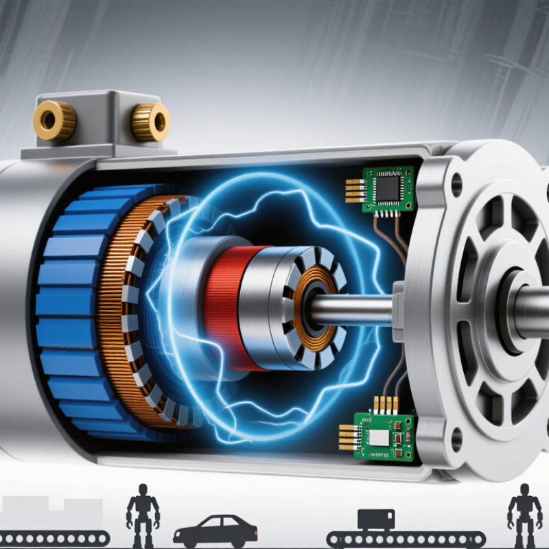
A brushless DC motor converts electrical energy into controlled rotary motion without mechanical brushes. Its main parts work as a coordinated system. The stator contains copper windings fixed around a laminated iron core. When current enters these windings, they create a rotating magnetic field. The rotor carries permanent magnets and turns inside that field. The rotor turns.

An electronic controller replaces the traditional commutator. It switches current between stator phases at precise moments. Position sensors can report the rotor angle to the controller. Some motors estimate position by measuring back electromotive force instead. This sensorless method reduces hardware, but it may respond poorly during startup or heavy loads. Timing matters greatly. Incorrect switching can cause vibration, noise, or unnecessary heat.

Bearings support the rotor and maintain a narrow air gap between moving and stationary parts. The housing protects the windings and helps transfer heat away from them. A heat path may include the stator core, casing, and mounting surface. During practical testing, temperature usually reveals problems before visible damage appears. Excessive current can weaken insulation over time. Poor alignment can also increase bearing wear, even when the motor seems electrically healthy. Engineers must balance speed, torque, cooling, control accuracy, and cost. No single component works alone, and that point is easy to underestimate.

How Electronic Commutation Produces Continuous Rotation

A brushless DC motor replaces mechanical brushes with electronic switching. Its rotor carries permanent magnets, while stationary coils form the stator. The key is electronic commutation: a controller changes current between phase windings as the rotor moves. This switching creates a rotating magnetic field that pulls the rotor forward. It is not truly seamless.

Position information usually comes from Hall sensors or estimated back electromotive force. When a sensor reports rotor alignment, the inverter energizes the appropriate phases. Current then flows through selected coils, producing a magnetic pole near the rotor magnet. A short electrical step becomes mechanical motion. As the rotor advances, the controller repeats this sequence many times each second. Pulse-width modulation adjusts average current, helping regulate torque and speed under changing loads.

In practical testing, correct timing matters more than fast switching alone. Poor timing can cause vibration, audible noise, extra heat, and reduced efficiency. Torque ripple may appear because the magnetic field changes in finite steps. Careful control softens these transitions, but it cannot remove every physical imperfection.

Sensorless control can be reliable at speed, yet starting and low-speed operation remain challenging. Temperature, friction, and sudden load changes also disturb the ideal commutation pattern. Engineers therefore verify waveforms, current levels, and rotor response during real operating conditions. The motor rotates continuously only because each controlled step arrives at the right moment.

Motor Control, Speed Regulation, and Operating Modes

A brushless DC motor uses electronic commutation instead of physical brushes. Its permanent-magnet rotor follows a rotating magnetic field created by stator windings. A controller switches these windings in sequence, producing torque with less mechanical wear. The timing must match rotor position.

Hall sensors can report rotor position directly. Sensorless control estimates position from back electromotive force, which reduces hardware but complicates starting. That distinction matters. At low speed, the signal is weak, so the controller may need a forced starting sequence.

Motor control usually relies on pulse-width modulation. The duty cycle changes the average voltage applied to the windings. A higher duty cycle generally increases speed and available torque. Yet speed does not rise perfectly with duty cycle. Load, winding resistance, friction, and temperature all interfere.

Operating modes serve different control goals. In open-loop mode, the controller follows a preset switching pattern. It is simple but may lose synchronisation under sudden loads. Closed-loop mode uses speed or position feedback to correct errors. During acceleration, it can increase current gradually and limit mechanical shock. Regenerative braking sends generated energy back to the power system, when the circuit supports it.

In practical testing, a motor may sound smooth but still run inefficiently. Small errors matter. I would verify current, temperature, and speed under real load, not only at no-load conditions. A reliable design also checks fault responses, because overheating can develop before performance visibly changes.

Brushless DC Motor: Three-Phase Trapezoidal Back-EMF

A BLDC motor commonly uses electronic six-step commutation. The three stator phases produce trapezoidal back-EMF waveforms that are electrically separated by 120°. The controller switches the energized phases according to rotor position to regulate torque and speed.

The vertical axis is normalized back-EMF, where 1.0 and −1.0 represent the positive and negative peak values. During regenerative braking or speed reduction, the inverter changes the phase-current timing and DC-bus energy flow while maintaining electronic commutation.

Advantages, Limitations, and Common Applications

A brushless DC motor uses electronic switching instead of physical brushes. Its rotor carries permanent magnets, while coils sit on the stationary stator. A controller energizes the coils in sequence, creating a rotating magnetic field. Position feedback may come from Hall sensors or back electromotive force. The rotor follows that field and produces continuous torque.

This design removes brush friction, sparking, and regular brush replacement. It usually delivers high efficiency, strong speed control, and quieter operation. That matters in a ceiling fan, where lower losses can reduce heat inside a closed housing. It also suits pumps, computer cooling fans, electric tools, robots, and precision machinery. Small. However, the motor is not automatically efficient in every system. The controller adds cost, wiring, and possible electromagnetic interference.

Sensorless control can struggle during startup or at very low speed. High temperatures may weaken magnets and shorten electronic component life. A suitable drive must match voltage, current, load, and required acceleration. An oversized motor can waste energy; an undersized one may overheat. A workshop check should measure winding temperature, vibration, and actual power draw. Datasheet efficiency is useful, but real airflow, friction, and duty cycles change results. That practical gap deserves attention before choosing this motor for a product.